
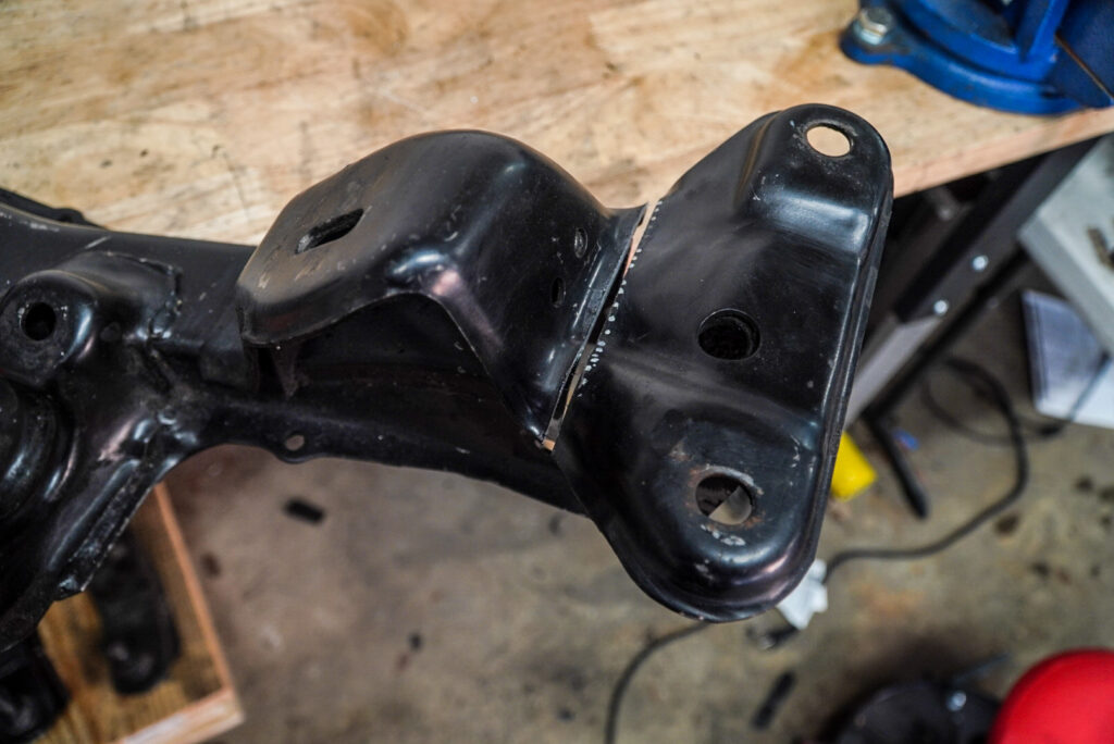
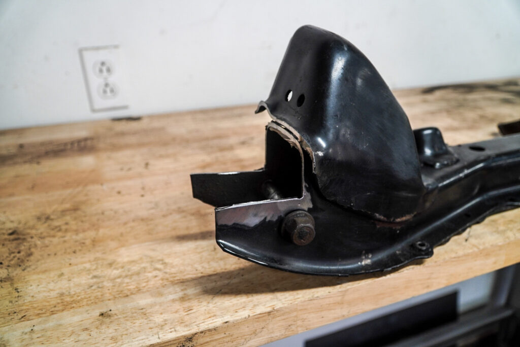
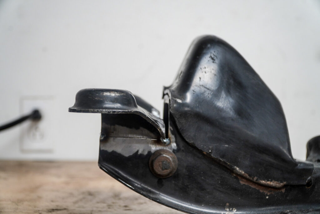
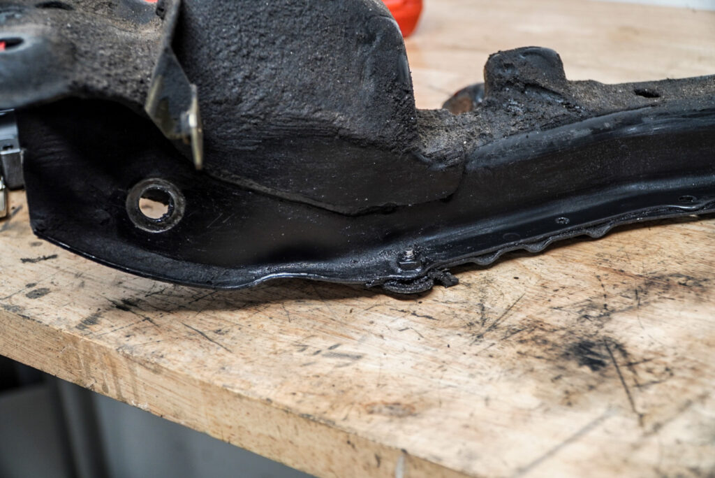
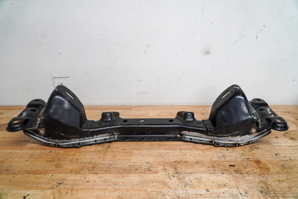
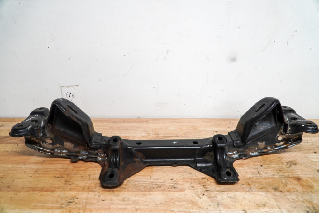
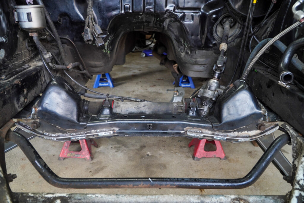
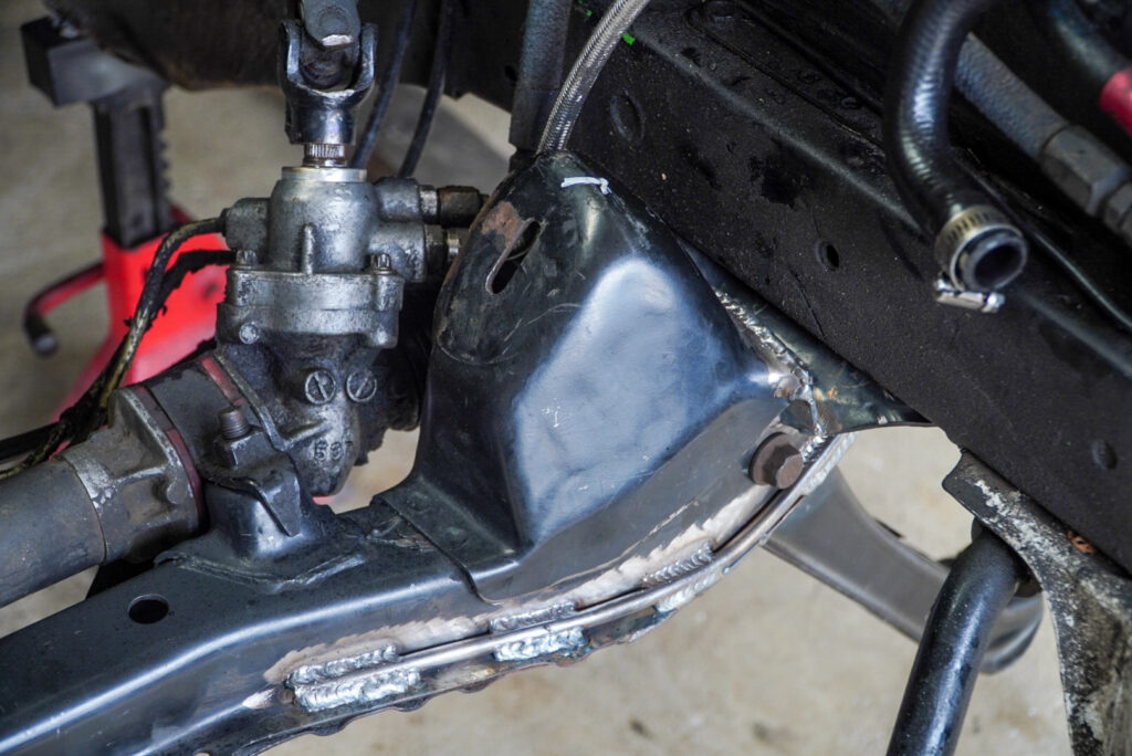
I was going to write a long-winded explanation on why sometimes I shuddered driving this car on the street, but the below photo does a pretty nice job of partially explaining the sensation I want to describe:
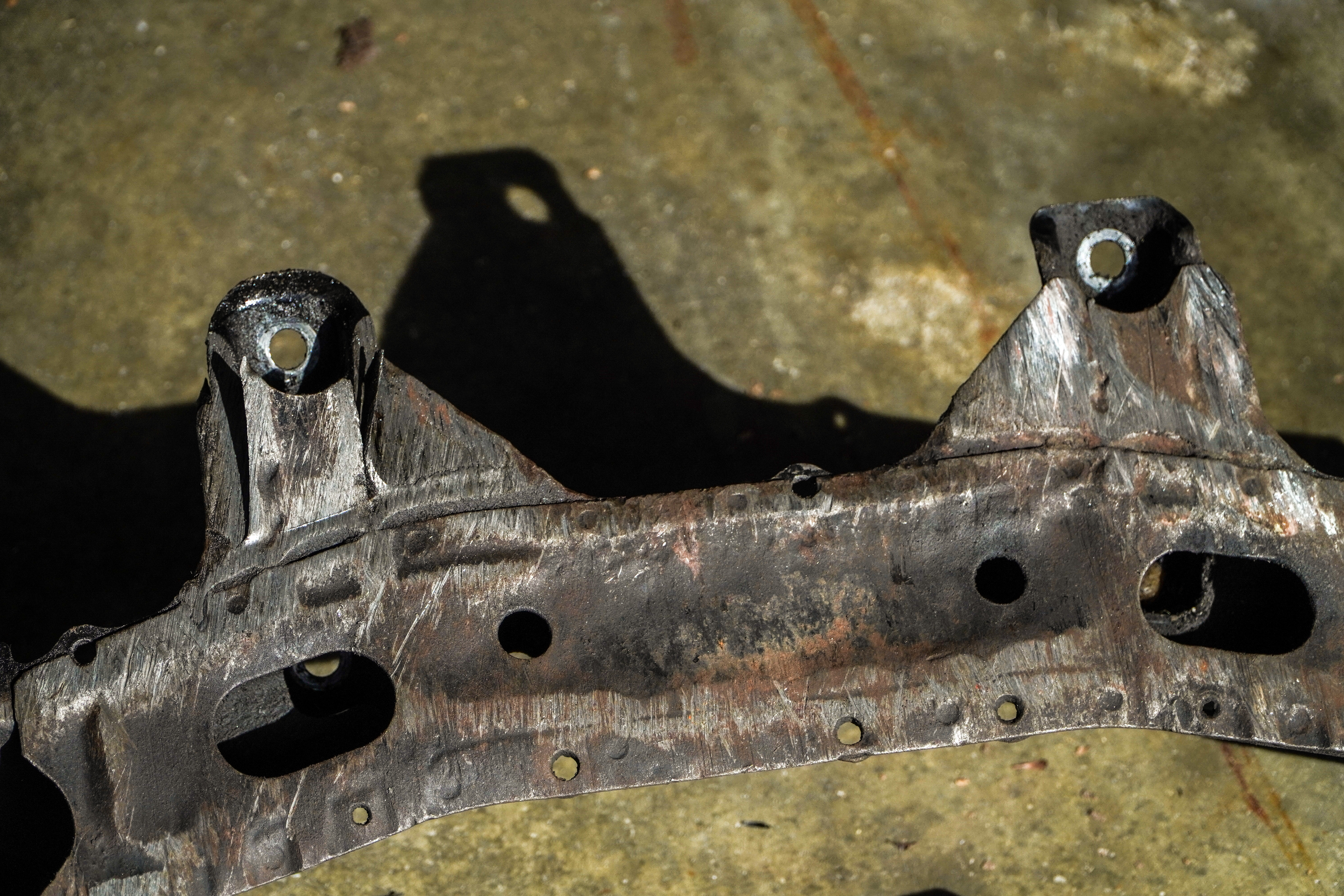
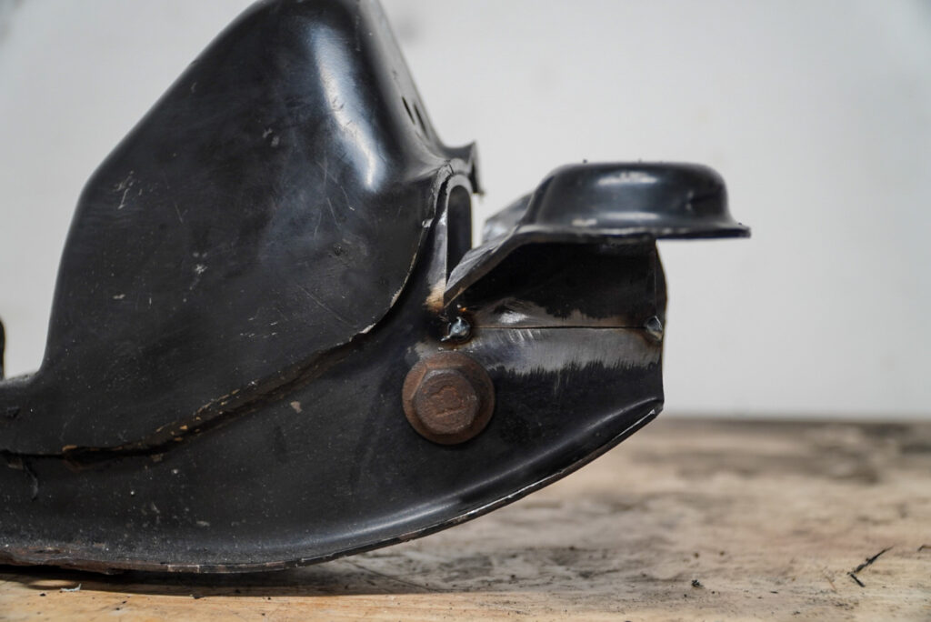
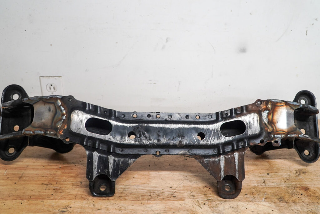
An s-chassis subframe is supposed to have a set of ridges on the bottom for strength. That piece that’s flopping on the left side of the photo is the lower brace for the steering rack. I essentially ground through this thing and I was worried that it would one day fall apart. These subframes are pretty poorly booger welded from the factory in some parts, and are quite thin. If you look closely, they’re really just four large pieces of metal welded together. Two mounds for the motor mount, the lower main piece, and the rack mounts. I don’t even think they’re 1/8″ because the metal I used for this project was thicker. I speculate the rationale was ease of production, and an integrated crush point in the event of a collision to protect the equally fragile frame rails in the engine bay.
I would like to get the front of the car a bit lower so I could also bring the rear lower, and this was the next limiting factor. All the smith grinds we’ve done on the road and on rumble strips really took a toll on this thing. When you start going down the path of heavily modifying your car by altering the unibody/chassis/subframes you start to think about solutions for problems differently. For example, thinking about an angle grinder and a welder as the solution to just about everything. The concept is pretty barbaric, but I’ve said it before and I’ll say it again – the best part about low cars aside from how sick they look, is the subset of problems created by the style that require creative thinking for solutions.
First thing was to measure out and plan the cuts. I went for a 35mm (1.4″) raise. The idea was cut a notch in the frame rail mounts, then remove 35mm of material. I had to be careful to not cut near where the control arm bolt touches the walls of the subframe.
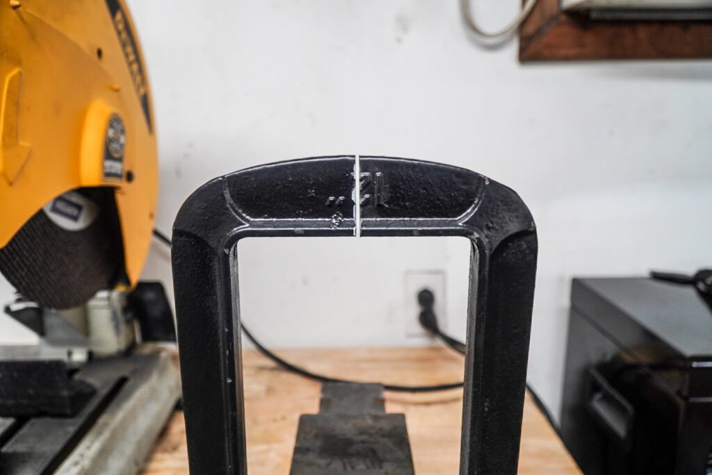
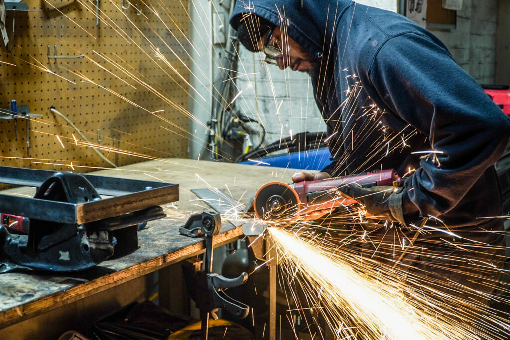
Next, I needed to make the cuts. I had to think about the best way to do this for a bit, so I had a few modelos. The first idea was to put a 12″ angle grinder blade on the 4.5″ grinder, then make a custom holding bracket for the sake of “safety.” Despite not having to be directly near the grinder when executing this absolutely asinine idea, this was still a pretty shitty idea. Then I saw the chop saw sitting in the car after using it to make the front control arms and this was the perfect tool to get an accurate cut.
Two issues with the chop saw: there was no safe way to get the subframe directly below the center of the blade for an even cut on both sides, and there was no safe way to clamp the subframe to the saw. Over the years I’ve learned to appreciate proper clamping and not half-ass this step. Strong clamp, clean cut.
To solve these issues I removed the built-in clamp to allow the subframe to sit in the center, then modified a massive $8 12″ C-clamp from harbor freight to clamp the subframe to the table and saw.
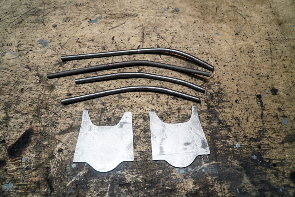
Welded two pieces of angle steel and shortened to match the edge of the clamp:
Here’s the final crusty setup:
The above atrocity worked out quite well!
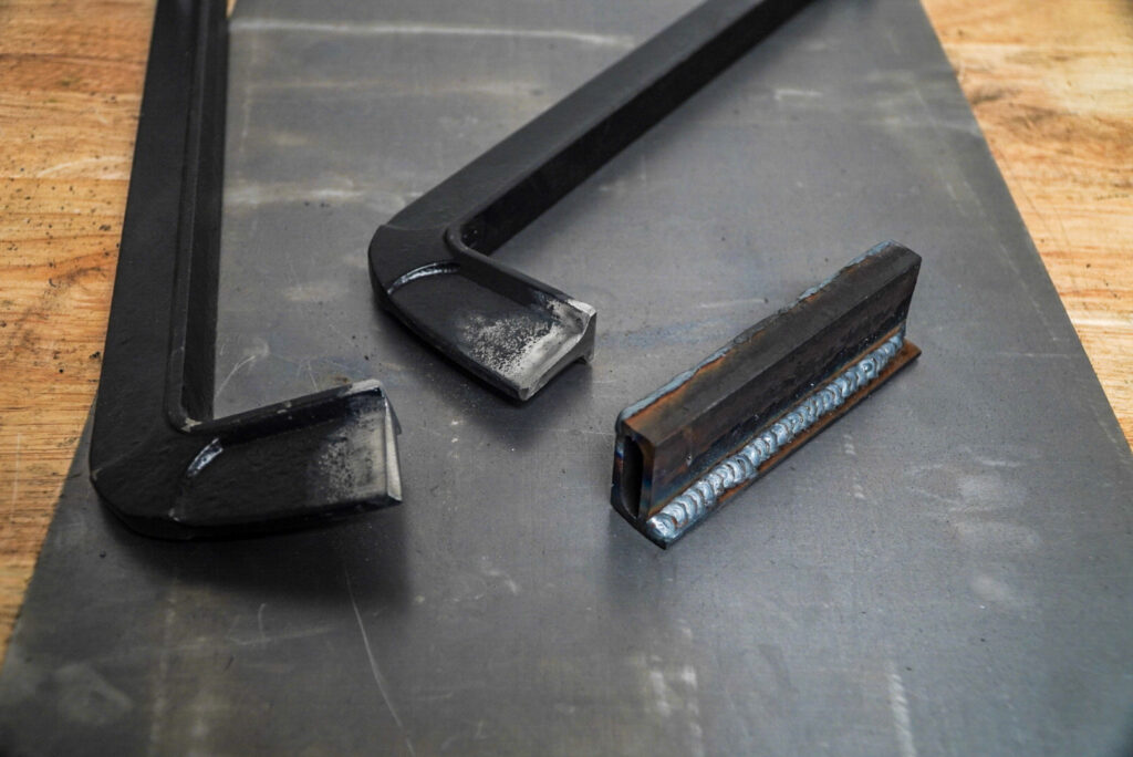
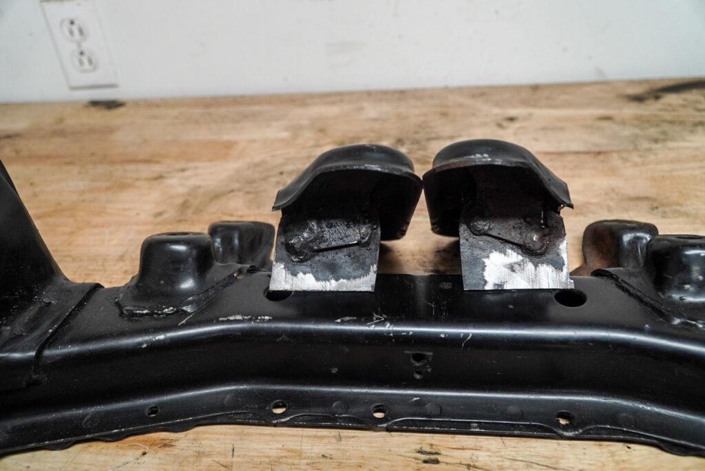
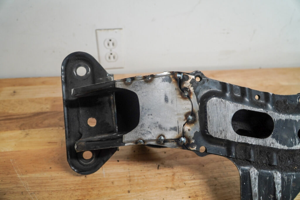
Here are the final complete cuts. The below photo also further exemplifies the multi-piece construction of an S-chassis front subframe. The motor mount “mound” is seam welded to the main lower piece at the bottom and SPOT welded on the top!! No wonder these things fall apart!
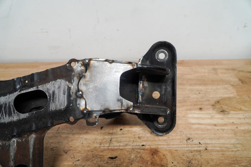
Here’s after trimming the 35mm

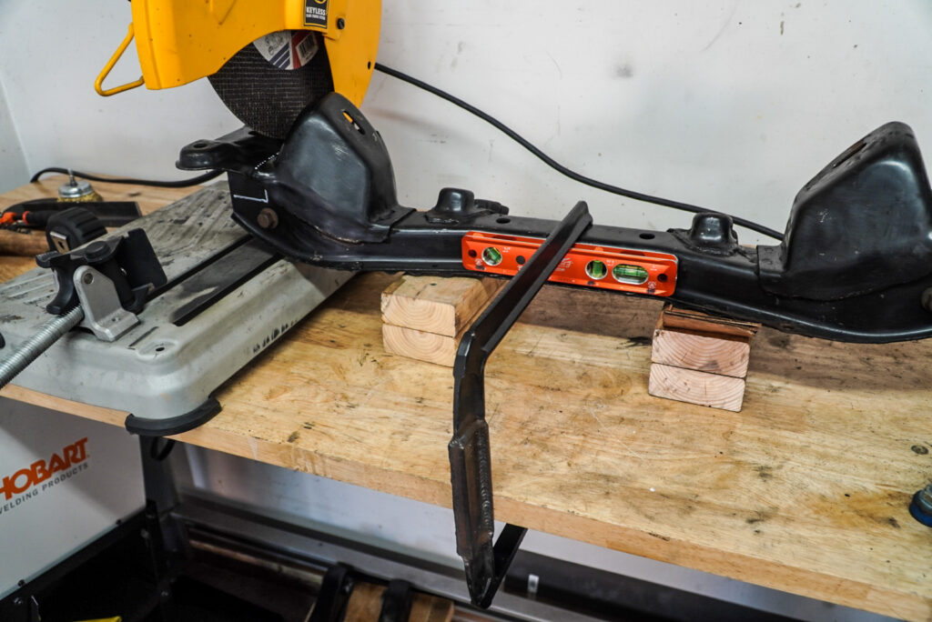
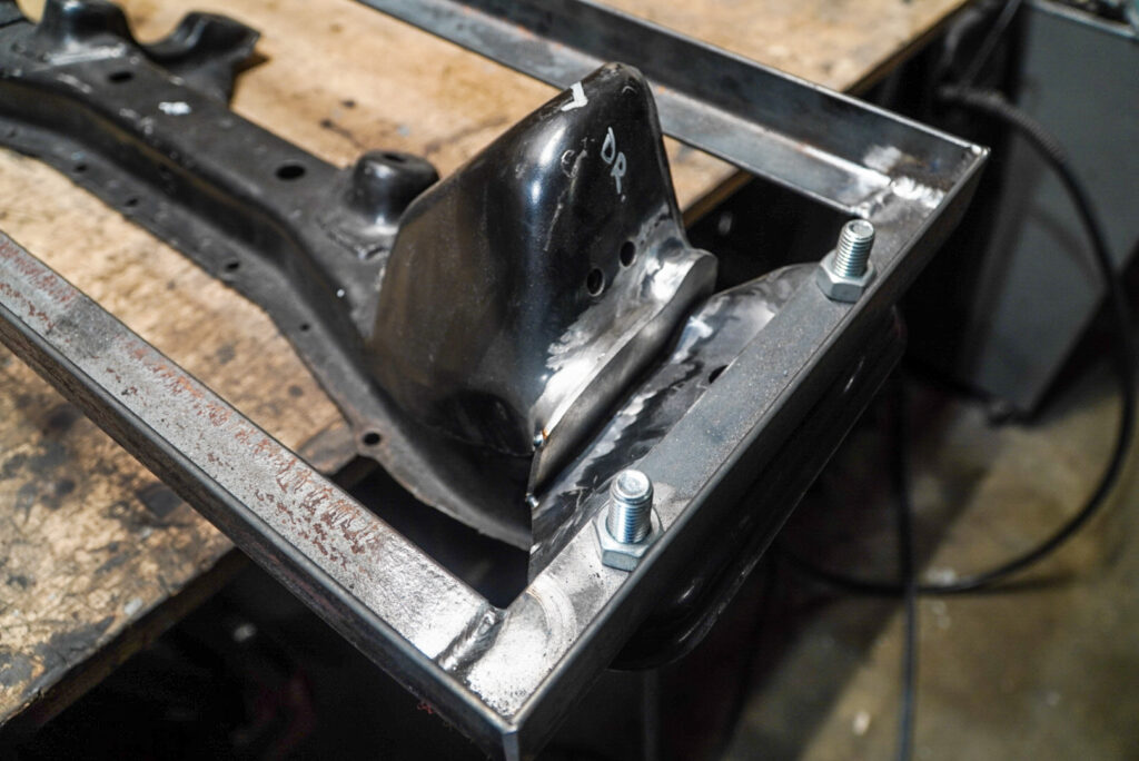
To tack these in, I spent hours creating a jig that resembled the frame rails on the car to ensure everything is even and welded straight. I did not want for the subframe to sit unevenly side to side or front and rear:
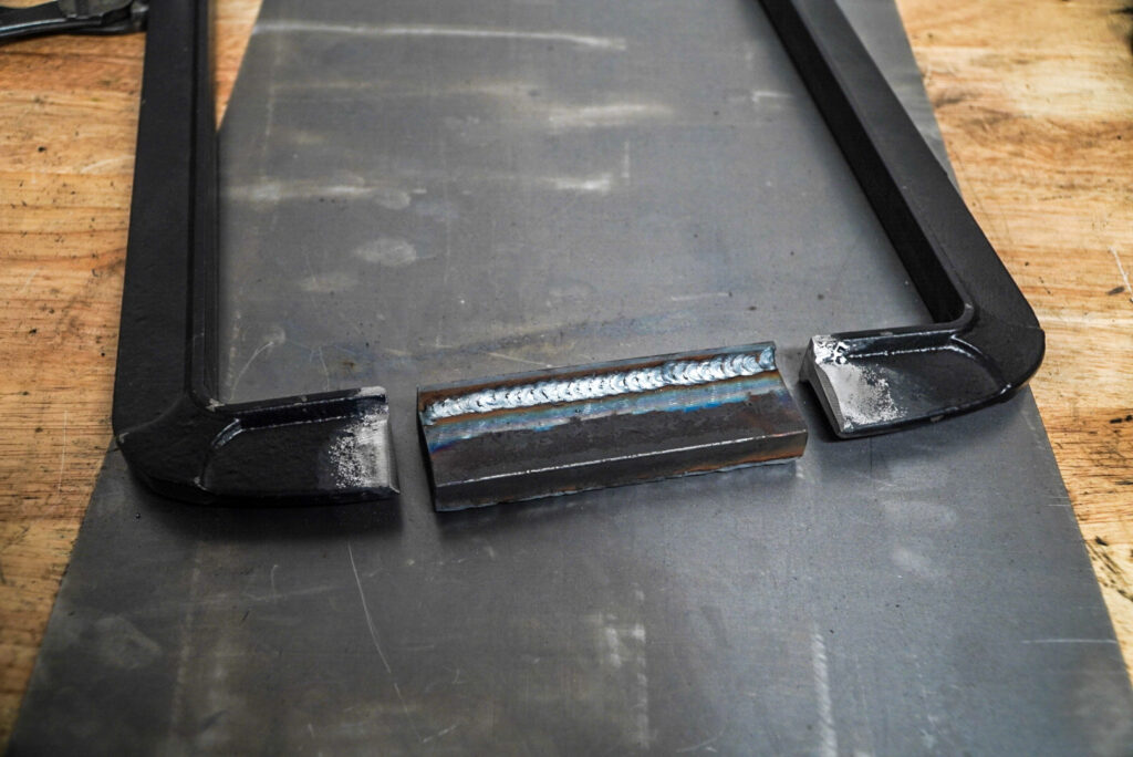
Next, I needed to create a piece to fill in the gap created by shortening the mounting point
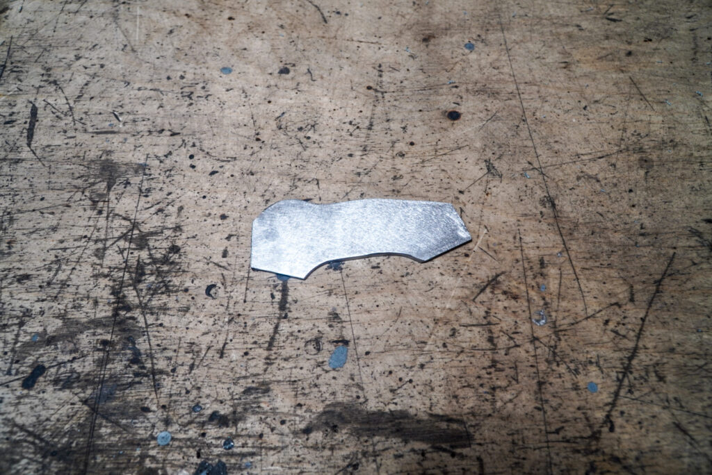
Here’s the piece tacked in and a photo of the jig I mentioned earlier. The bolts are the exact size of the studs on the front subframe hangers. This should ideally match the position of the frame rails on the car within really tight tolerances.
I’ve been messing with the settings on my camera and I changed the focus mode. As you’ve probably noticed, a bunch of the photos on this post, and some in the prior, are not focused properly and look a little soft. The issue should be resolved now, but it’s unfortunate. Anyway, welding them in:
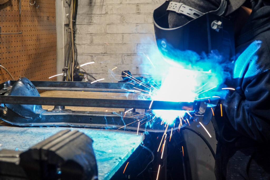
These were super fun to weld
Next, I test fitted the subframe on the car and everything lined up perfectly without binding. The only issue was the newly raised portion of the subframe greatly decreased clearance for the rearmost portion of the front lower control arms. Luckily, these arms have a good bit of unnecessary extra material on the top. Remember what I said earlier about solving problems with angle grinders?
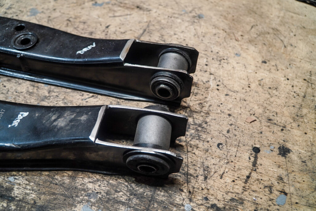
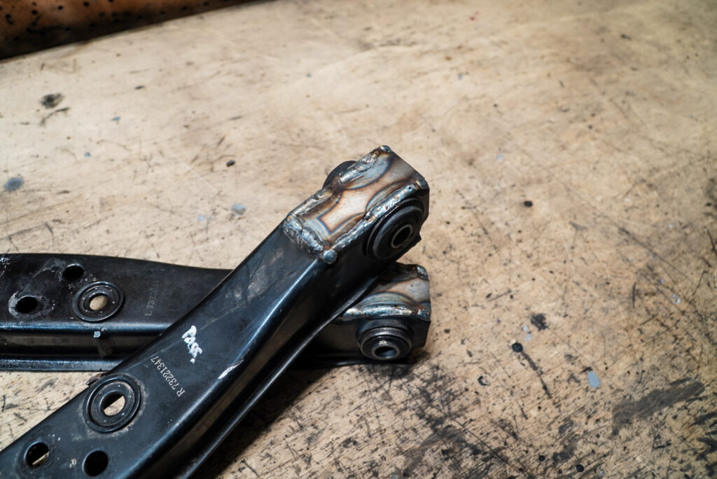
Welded flush for maximum clearance:
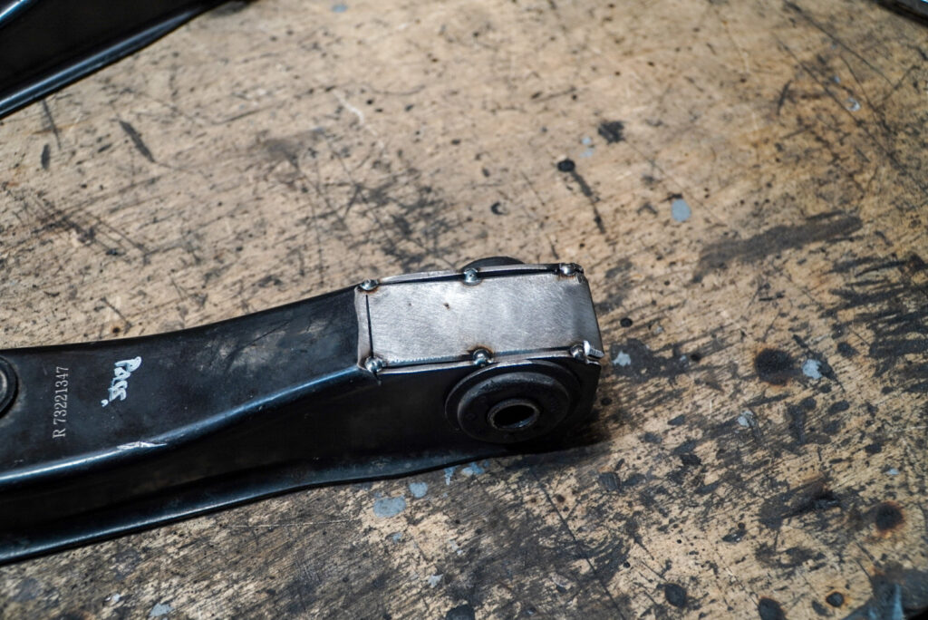
I had to be extra careful distributing the heat of the weld to not smoke the bushings. I ended up welding a short bead, then cooling the bushing with compressed air and water. They held up fine without signs of premature deterioration, but time will be the ultimate test:
I elected to not brace the bottom to leave a failure point in the front suspension. I’d rather make a new arm than a new subframe. Speaking of bracing, I needed to protect the investment of time I put into this thing. After bending two subframes, I needed this one to last. This is also going to be an integral part of the car going forward since we’ll need to make a hell of a lot of changes to pieces around the engine for this thing to work. Meaning, if this bends, I’ll have to make another – which I really want to avoid. I don’t see any kits like this offered in the current market – would be cool if someone manufactured these.
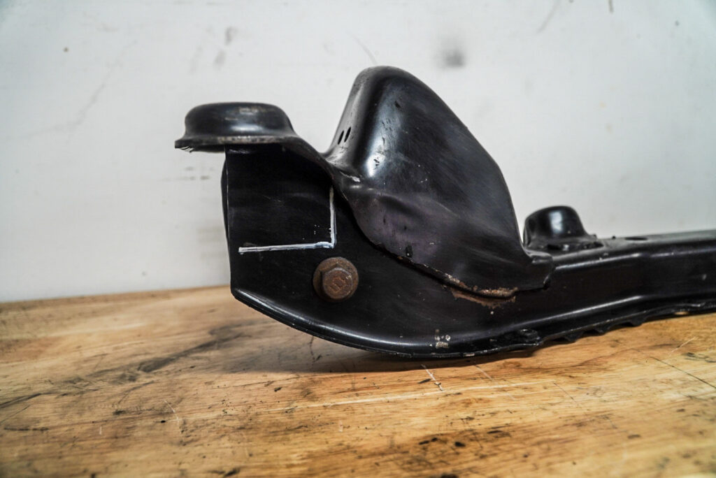
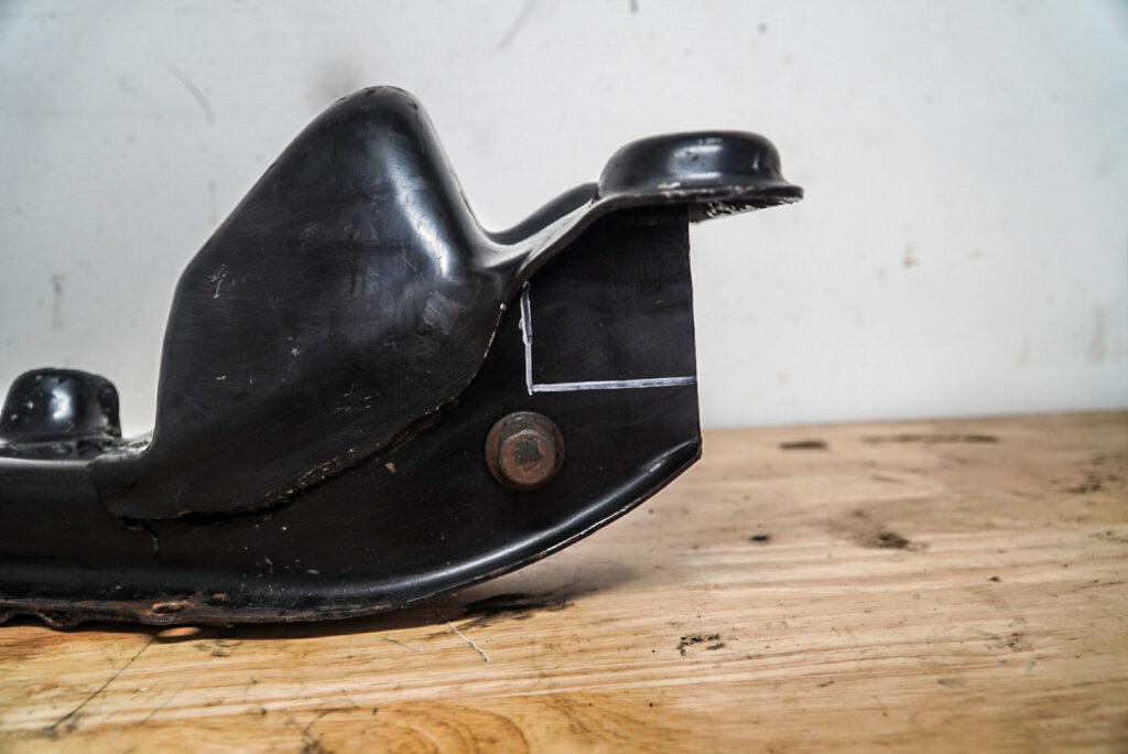
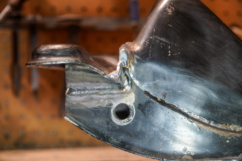
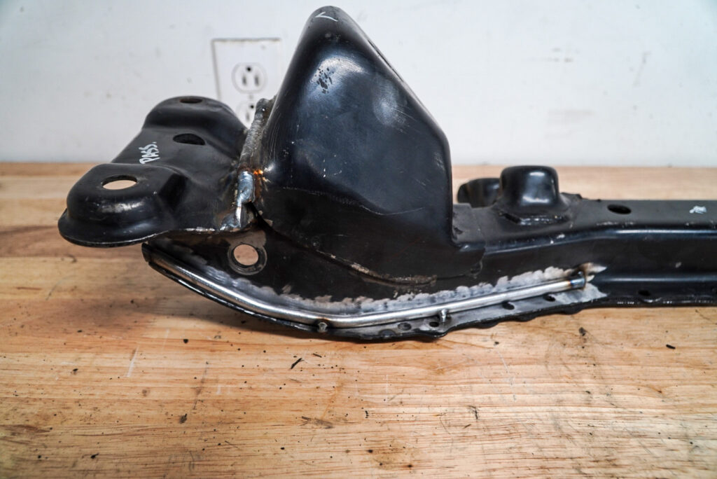
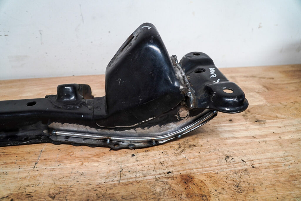
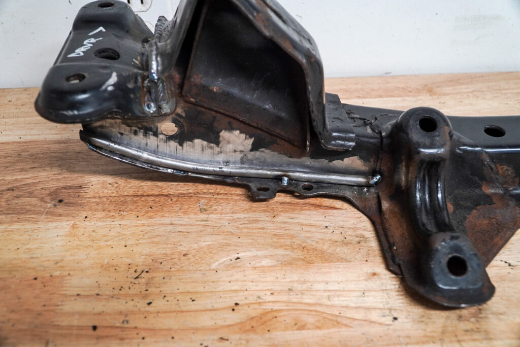
These subframes tend to bend where the front lower control arm mounts since it’s essentially only two thin pieces of steel that form a channel. When the subframes bend, they tend to kink around the edges, see below for an extreme example featuring Nick’s subframe:
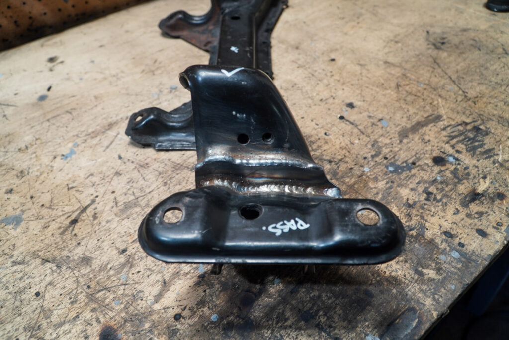
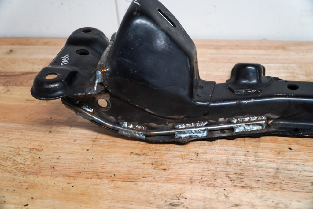
The front braces tacked in:
Rear as well:
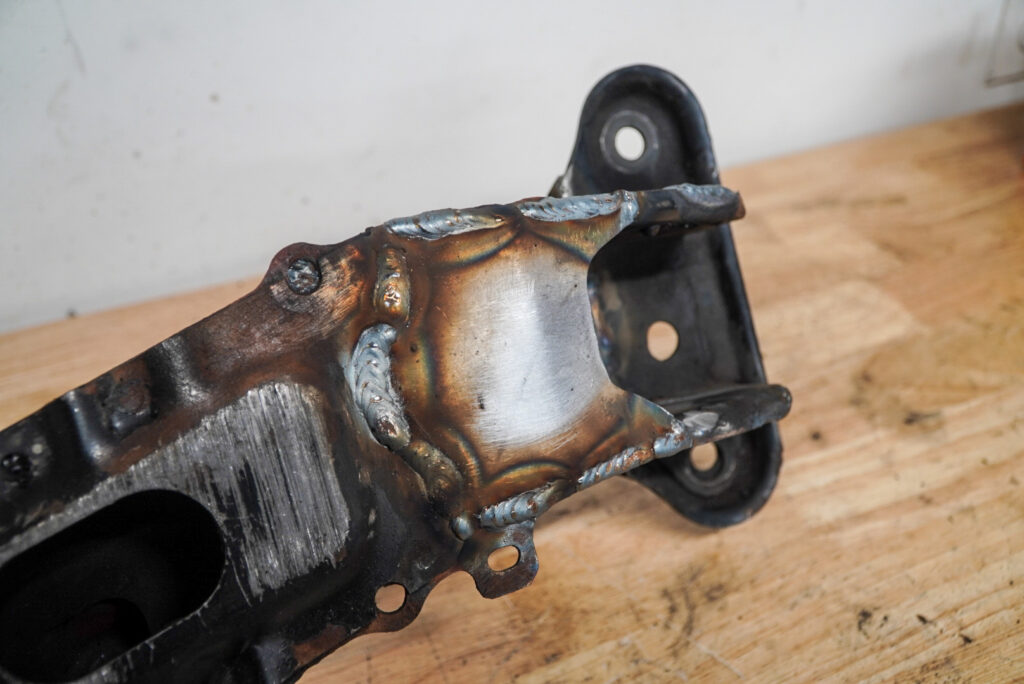
Fully welded:
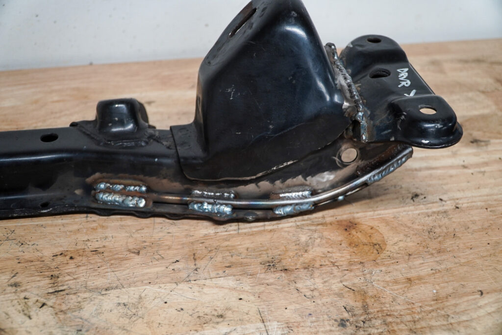
This lower brace is critical to protecting the subframe from bending. Same idea as the GKTech Hopefully this sends the force of impact to the front control arms and tie rods!
Here’s the final result:
Finally, I needed to test fit the subframe on the car with the control arms. I was a bit nervous about this bit since I put a lot of faith in the jig and this would reveal any fuckery that occurred while measuring/making the jig.
Final fit went well and the subframe went up and down with 0 binding on the hangers/bolts!
The steering joint is extremely close to binding so I’m going to need to shorten that or hammer it further into the shaft for more clearance.
I’ll need to paint/epoxy/fluid film this thing and we’ll be all set for a final install. With this setup, the rear diff is raised ~50mm with the subframe risers and the diff raise. The front subframe is raised 35mm. This likely has the pinion angle totally fucked, and especially fucked given I run a one piece driveshaft. In the next installment, I’ll explain how we’re going to address it. Stay tuned!
Thanks for reading
Juan